BIC Process Design
Understand & Transform
Supercharge your business operations with the most intuitive AI-powered BPM software.
It seems that you come from a German speaking country. Here you can change the language
EnglishProducts by GBTEC
BIC Process Design
Understand & Transform
BIC Process Design
Understand & Transform
Supercharge your business operations with the most intuitive AI-powered BPM software.

BIC EAM
Structure & Streamline
BIC EAM
Structure & Streamline
Reduce IT costs and accelerate your IT transformation with our intelligent EAM solution.

BIC Process Execution
Automate & Orchestrate
BIC Process Execution
Automate & Orchestrate
Redefine the way you work with record-breaking workflow automation.

BIC Process Mining
Reveal & Accelerate
BIC Process Mining
Reveal & Accelerate
Unlock crucial insights from hidden process data and swiftly eliminate weak points.

BIC GRC
Secure & Comply
BIC GRC
Secure & Comply
Explore our comprehensive GRC platform tailored to meet your needs.

Use Case
Understand & Transform
BIC Process Design
Process Excellence
Optimize your workflows for maximum performance and efficiency.
Digital Transformation Projects
Pave the way for your digitization project with a process-driven approach.
Integrated Management System
Align various management systems and leverage synergies.
Quality Management
Set new standards for excellence in quality management.
SAP S/4HANA Transformation
Successfully navigate SAP S/4HANA migration or implementation projects.
Structure and Streamline
BIC EAM
Business Enterprise Architecture
Align your business strategy and IT landscape in perfect harmony.
Business Capability Mapping
Gain clear insights to seamlessly align strategy, processes, and IT.
IT Landscape Transformation
Transform your IT landscape to agilely navigate the digital transformation.
IT Rationalization
Optimize your IT landscape for maximum performance and efficiency.
Technology Risk Management
Protect your business from risks and foster stability for innovation.
Automate & Orchestrate
BIC Process Execution
HR Workflow Automation
Shape the future of Human Resources with automated processes.
IT Workflow Automation
Relieve your IT department from time-consuming routine tasks with automated workflows.
Approval Workflow Automation
Automate your approval workflows and accelerate decision-making.
Forms Automation
Simplify data collection and processing with automated forms.
Secure & Comply
BIC GRC
ESG Management
Enhance social responsibility and environmental impact while adhering to governance standards.
Outsourcing Management
Keep the security of your outsourced processes in mind at all times.
Risk Simulation
Proactively simulate risks and be prepared for potential crisis situations.
Compliance Management
Monitor compliance, mitigate risks, and quickly adapt to new requirements.
IT and Cyber Security
Manage IT risks, comply with regulations, and protect your most valuable company assets.
MaRisk
Benefit from comprehensive risk management to fulfill BaFin's requirements fully.
Industries
Automotive
Gain new insights for excellent processes and an improved customer experience.
Education & Universities
Spot improvement potentials in your administrative and teaching processes effortlessly.
Energy & Utilities
Uncover bottlenecks and potential savings in your processes systematically.
Finance & Insurance
Create secure and reliable processes in a highly regulated environment.
Healthcare
Improve efficiency through optimized, digital processes in healthcare.
Logistics
Optimize supply chains and uncover potential savings in your supply chain processes.
Manufacturing
Exploit the potential in your procurement, production, and transportation processes.
Pharma & Chemistry
Enhance your processes and ensure compliance with regulatory standards.
Public
Accelerate digitalization and pinpoint areas for process improvement.
Real Estate & Construction
Unlock potential savings in marketing and administration of your construction projects.
Other Industries
Unlock significant cost savings while simultaneously boosting process efficiency.
All Resources
Webinars & Events
Whitepaper
Wiki
Process Management
Accelerate growth. Optimize your business processes for peak performance.
Enterprise Architecture
Align systems, drive efficiency. Transform your enterprise for the future.
Process Automation
Work smarter, not harder. Let automation enhance productivity and drive your success.
Process Mining
Shine a light on your processes. Discover inefficiencies and power your progress.
Governance, Risk & Compliance
Protect what matters. Strengthen your operations with structure and security.
Success Stories
Product Information
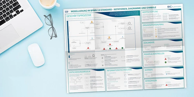
BPMN is the abbreviation for Business Process Model and Notation and a globally accepted language for business process modeling. It provides a graphical portrayal of working sequences and their interaction with one another. This representation makes it easier to comprehend performance collaboration and economic interactions between organizations and for stakeholder to quick ly react to new internal and external business situations.


BPMN is a graphical notation for process modeling and describing business processes in a business process diagram (BPD). As an essential component of BPM, it enables organizations - irrespective of company size or industry - to visualize and optimize their business processes. By utilizing this modeling language, working steps are represented consistently and thus easily comprehensible for all process participants. It aims to facilitate business process management for both technical and business users, analysts, technical developers, and business managers adopting a similar language for describing processes and preventing communication gaps that may occur between business process design and implementation. Thus, the communication of processes is simplified across the entire organization. BPMN was developed in 2001. After numerous revisions, the Object Management Group® (OMG) published BPMN 2.0 in 2010. The metamodel also includes an execution semantics that can be utilized for the technical automation using a process engine.
With the help of professional software, the Business Process Model and Notation provides considerable added value for organizations. BPMN 2.0.1 has also been established as a norm (ISO/IEC 19510:2013). It is meant to be utilized directly by stakeholders involved in designing, managing, and implementing business processes while also being accurate enough to enable the conversion of BPMN diagrams into software process components. To sum it up: BPMN offers an intuitive notation that resembles a flowchart and is independent of any specific implementation environment.
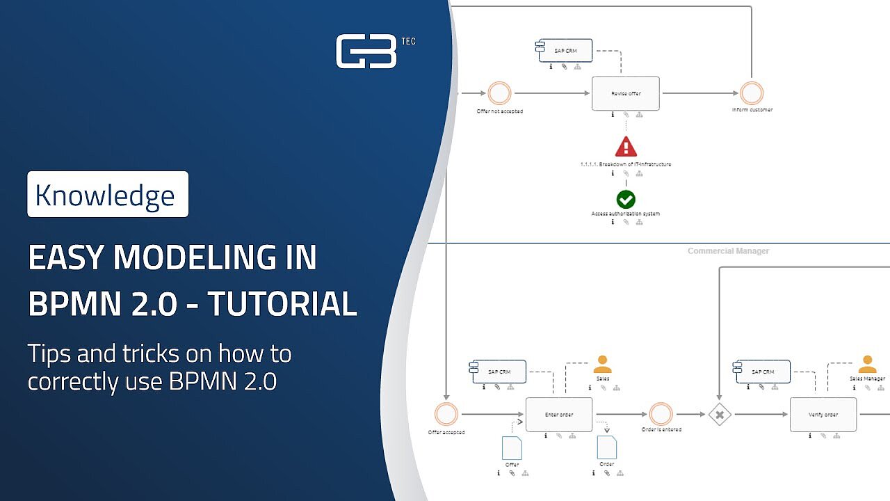
Using the BPMN standard for process modeling allows for an effective representation of business processes with a flow chart method that models the steps of a planned business process from end to end. To build a BPMN diagram, you initially need to create a pool, which can be divided into any desired number of lanes. Depending on the selected diagram type, it is also possible to create multiple pools. Process modeling always begins with at least one start event and ends with one or more end events. The process in between the start and end events consists of additional events, activities, gateways and other artifacts. Precise modeling guidelines ensure the correct use of the elements and consistent documentation of processes, help boost productivity and adjust to changing conditions, or to gain competitive advantage.
With the intuitive modeling tool of BIC Process Design, you can also use other modeling languages such as DMN (Decision Model and Notation), VCD (Value Chain Diagram) or EPC (Event-driven Process Chain) to build your process map.
Generate industry-specific BPMN diagrams effortlessly and flawlessly with our groundbreaking AI-powered feature in BIC Process Design by simply entering commands. Experience a revolutionary approach to process modeling and boost your efficiency sustainably. Save yourself time and effort and benefit from greater consistency in your process models.
BPMN 2.0 contains a large number of elements. BIC Process Design's intuitive BPMN tool provides these elements in such a way that you can start modeling immediately.
Events are occuring, business-relevant states. In BPMN 2.0, events can either start a process, occur, or be caused during a process, or end a process. Events that have occurred are conditions created by an external trigger. These can be start or intermediate events. Triggered events are conditions generated by the process itself, these are intermediate or end events.

Start event
The start event triggers the sequence flow of a diagram.

Intermediate event
An intermediate event pauses the sequence flow. It is only resumed when the event has occurred.

End event
End events terminate the sequence flow of a diagram.
Model activities to represent individual process steps in BPMN diagrams.

Activity
An activity represents a single work step and is expressed in active form.

Sub process
If you do not want to show the complex sequence of an activity directly in the BPMN diagram, you can avoide this by creating a sub process. A sub process is a flowchart that provides a detailed description of complex activities on the next level.
Usually, processes are not always linear, but consist of splits and mergers. Within the process flow, these are represented by gateways.

Exclusive gateway
Exclusive gateways are used when only one condition can occur ("either/or"). When merging, exactly one incoming process path must be satisfied.

Parallel gateway
Forparallel gateway, all outgoing process paths must be satisfied ("and"). The process flow can only continue if all incoming process paths have been fulfilled.

Inclusive gateway
Inclusive gateways are used when one or more process paths can be followed ("and/or"; combination of paths). When merging, all previously triggered paths must be waited for.

Event-based gateway
In the case of event-based gateways, the process flow whose event occurs first is followed.
All flow elements used in a BPMN process are connected by so-called sequence flows.

Sequence flows
Sequence flows connect the activities, events and gateways of a process and thus illustrate the chronological sequence of the process.

Message flows
Message flows represent the exchange of information with external process participants. They are triggered by activities and can be attached to other activities, pools, or new events.
The individual steps of a process are performed by process participants. In BIC Process Design, these are represented as organizational units, roles, IT systems and services. Following the BPMN standard, users model within pools and lanes to represent the different process participants.

Pool
Pools represent a superior process participant, that coordinates the process flow within the pool. They cover the entire process and assign tasks to the responsible lanes.

Lanes
Pools are usually further subdivided into lanes. Lanes represent process participants, which can be organizational units or roles. In BIC Process Design they are created by defining a pool in the editor. The individual tasks of the process participant are then modeled within the corresponding lane.
To make the design of your business processes in BPMN even clearer, additional artifacts are part of the BIC standard for modelers.

Data Objects
Many processes contain process steps that involve the use or creation of documents or data. These are represented by data objects. Data objects can be paper documents as well as electronic data.

Annotation
All BPMN elements can be annotated to provide a better understanding of the process model. The annotation is placed directly in the process.

Group
The group is a visual element, that summarizes content-related objects. This helps to better understand the model without affecting the process flow.

Role
A role in BPM is an abstraction of organizational positions or a summary of the same fields of activity. Process participants other than those modeled as lanes can be represented as roles.

Application
Applications represent IT systems that are relevant for the execution of process steps. They explicitly show which IT systems are used to support manual work.

Norm
Norms represent requirements for process execution. They can be company-specific guidelines or official, international standards.

Risk
Risks are hazards that can occur during process execution. They are used in BPMN modeling to support process-oriented risk management.

Control
Controls are regulatory activities aimed at minimizing risks. They are used in BPMN modeling to support internal control systems.
BPMN is a universal notation that is used in various business areas to leverage optimization potential and automate processes, such as:
BPMN helps companies to improve processes, reduce costs and increase efficiency by providing a clear and consistent method for modeling and analyzing business processes.
BPMN depicts complex processes and deals with this issues. Grafical process diagrams promote increases communication between various teams. Like this you can get a clear picture of how a complex business process operates from end to end, streamline processes, improve their efficiency and at the same time decrease the amount of time employees spend on repetitive tasks and mistakes.


Head of GBTEC Academy
Christoph isn’t just the head of our GBTEC Academy – he also brings years of experience and deep expertise across our entire product portfolio. For many years, he worked closely with our customers as a consultant. Today, he and his team provide not only product-specific trainings but also help companies and professionals strengthen their skills in a wide range of topics, even beyond our own product offerings.
GBTEC Software AG
Gesundheitscampus-Süd 23
44801 Bochum
Germany